
CubeSat Deployer

CubeSat Deployer
A CubeSat is a standard cubic box that can be tailored to hold a desired payload. The CubeSat deployer mechanism essentially deploys a smaller series of Printable Circuit Board satellites (PCBsats).
STAC is interested in this technology because recent work on directed energy propulsion of small wafer-scale spacecraft has enabled a technically-sound conversation on achieving relativistic interstellar spaceflight. This work comes out of NASA-funded work through the NASA Innovative Advanced Concept funded programs DEEP-IN and DEIS, led by Professor Philip Lubin of the UCSB Experimental Cosmology Group.
One of the first steps to achieving this grander scale innovation in interstellar travel requires the use of laser communication. Our CubeSat deployer project runs a proof-of-concept and provides initial framework for laser communication by designing and fabricating an incremental deployment of PCBsats.
CubeSat Deployer Prototype
The CubeSat project is a satellite mission to investigate the technological feasibility of point-to-point laser communication in Low Earth Orbit (LEO). There is currently no infrastructure for inter-satellite data exchange in space -- something much-needed with the strong intentions industry leaders and investors have shown in deploying constellations spanning thousands of satellites. Currently, if Alice (a satellite in LEO) wants to speak to Bob (another satellite in LEO), information has to be passed down to Alice’s gateway (on Earth), through the internet to Bob’s gateway (also on Earth), and then back up to Bob. Point-to-point data links between satellites in LEO provides a low-latency alternative for orbiting spacecraft to communicate with each other. One of the strongest candidates for point-to-point communication in space is laser technology. We are proposing a 3U CubeSat that will deploy several smaller Printed Circuit Board (PCB) satellites and then establish laser communications with them using closed-loop feedback control. The challenge being addressed by the STAC CubeSat project is how to best achieve the high pointing accuracy required by laser communication systems. Our goal is to empirically quantify the performance of laser closed-loop control algorithms and assess the capabilities of the self-orienting PCBSats.

Figure 1: Artistic Rendition of CalSat Deployer of PCBSats
Attitude Determination and Control Systems
In order to be able to orient the CubeSat and the PCBSats we require precise and active control systems. The CubeSat will use a combination of magnetorquers and momentum wheels to accurately point in the desired direction. The magnetorquers will be primarily used to detumble the CubeSat after deployment. The momentum wheels will provide an active control system whilst in orbit to in order to deploy the PCBSats in the correct direction. We will use self-designed magnetorquers on the PCBSats to orient their lasers towards the CubeSat receivers.
Software and Communication
The software subteam is primarily responsible for communications between the satellite and ground station as well as laser communications between the CubeSat deployer and individual PCBSats. The team is also responsible for writing software to control the onboard microcontroller and satellite states. Incoming sensory data, ground communications signals, and PCBSat signals are collected and analyzed to control internal hardware and send outgoing communications; this divides the role of the software into: data input, output, and error correction.
Power Systems
The main objective is to develop a power system for the CubeSat. All systems on the CubeSat are powered by LiPo battery banks, which are charged periodically by solar panels on the outside of the chassis. The battery banks provide more than 7.5 Volts, which can be further divided to supply different subsystems. The power system PCB also manages charge cycles and power distribution to ensure the functionality of other subsystems during both the sunlit and eclipse periods of the orbit.
Electronics
Proposed electronic components of the Cubesat command and data handling (C&DH) board are:
- CPU (either a processor or microcontroller)
- Running a Linux real-time operating system (RTOS)
- NAND and/or NOR Flash memory
- SRAM and/or SDRAM memory
- Serial communication (SPI, I2C, UART, RS-422, etc.) capabilities
- 3.3V and 5V Voltage regulators
- Uplink/Downlink communication bus
- Digital I/O and Analog sensing capabilities
- Stackable connector pins
- Backup battery
- Radio
Testing Prototype
With our partnership with the Space Sciences Laboratory (SSL), we will be running vibration tests and thermo-vacuum chamber tests at the SSL facilities.
Goals of CubeSat Deployer
- Provide cost effective and flexible test platform for developing spacecraft and communications technology
- Allow for integration of various sensor systems to support data capture and manipulation
- Utilize readily available materials and integrated circuits to support quick revision turnaround times and system re-designs
- Explore the limits of rigid PCB manufacturing capabilities for future use
- Test and validate early-life directed energy technologies
- Test and validate early-life propulsion and orientation systems
- Test and validate CalSat Deployer on Earth in the lab and with balloons at high-altitudes
- Test controls for CubeSat and PCBSat with UC Davis SSS Air Bearing and with SSL facilities
- Provide a starting point from which future revisions/systems can be based on
- Provide an inexpensive platform to deploy multiple experiments in a single launch
- Produce data, feedback and calculations in order to drive future development
PCB Spacecraft Prototype (UCSB and STAC)
Because the PCBsat fabrication is done with our partner at UCSB, more details on PCBsat specs can be found on their site.
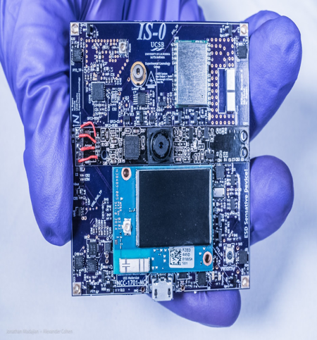
Figure 2: Initial revision of waferSat on a PC Board
Above is the initial revision of waferSat on a PC Board developed at UCSB. It includes subsystems for altitude control, digital image acquisition, inter-system communications, and photovoltaic power source.
Development Path and Timeline
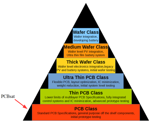
Figure 3: Evolution of PCBSats to Wafer Spacecraft for Interstellar Travel
- Develop and 3D-print initial CalSat design
- Develop electronics and power for CalSat
- Develop Altitude and control systems with suntracker and torque coils
- Test PCBSat on ground with UCSB
- 2nd prototype of CalSat deployer
- Combine electronic avionics with CalSat deployer
- Develop comm-link for ground
- Raise funding and awareness for the CalSat
- Testing prototype at SSL
- Fix any prototype flaws
- Prepare for launch - mid 2020